Feed-line pass-through and grounding
I recently cut a pass-through for my home radio station.
Outside of a simple hole for my feed-lines to enter the house, the pass-through configuration solves three separate but related issues:
- Preventing ground loops and in-shack RFI with a copper ground bus and braid
- Lightning protection from the antenna with an arrester, copper sheet and bonding conductor
- Electric shock protection inside the shack provided by code compliant grounded power
All of these systems connect to bonded grounding rods at my electric service entrance so they share a common ground.
My station is in the finished portion of my basement. My foundation walls are high and extend about 3 feet above grade. The plan was to drill a large hole through the foundation wall into an electric utility closet that sits next to my radios. Inside the basement the pass-through hole is about 7 feet above the floor.
A little help from my friend
Step one was reach out to my friend Ken who knows a ton more than I do about construction and had a drill that could penetrate cement.
He used a large drill bit to cut a hole through 8 inches of cement foundation. We didn’t have a cookie cutter attachment so we just enlarged the hole by “stirring” the drill after we cut through. We were able to bore out a conduit large enough for three or so coax lines, more than enough.
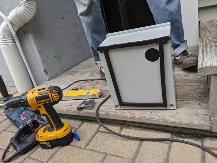
Once the pass through hole was cut we measured and drilled pilot holes to mount the entrance panel.
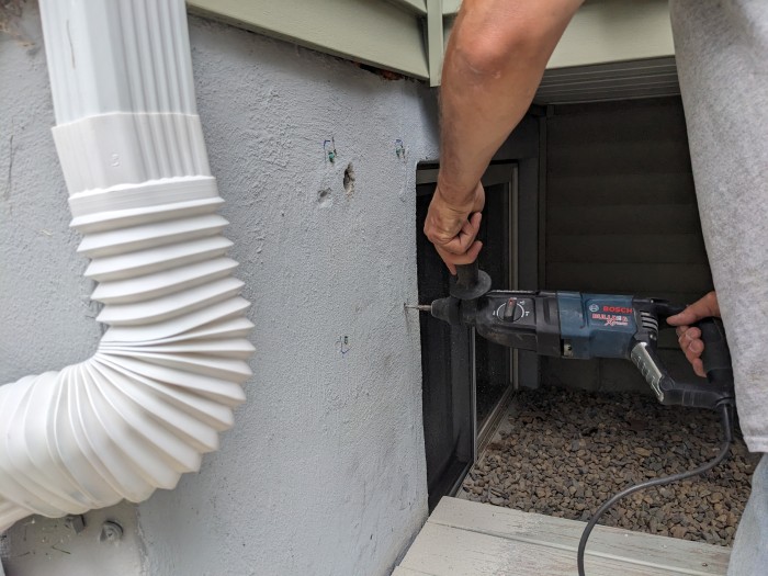
Here Ken is using the same drill with a smaller bit for the pilot holes.
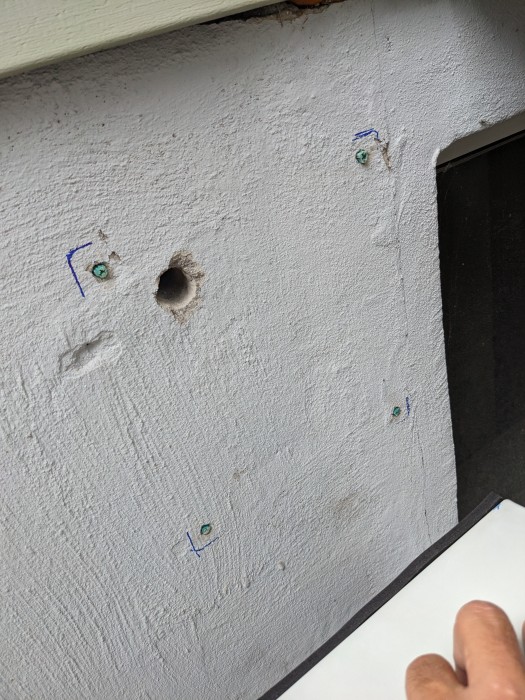
Placing the mount points was as simple placing and leveling the box, tracing the corners with a Sharpy then measuring in from the marks.
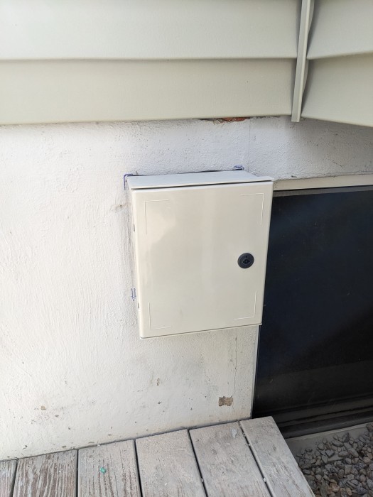
Phase one complete! The box is mounted and ready for me to install and connect grounding components.
Grounding and lightning protection
The next weekend I completed the project.
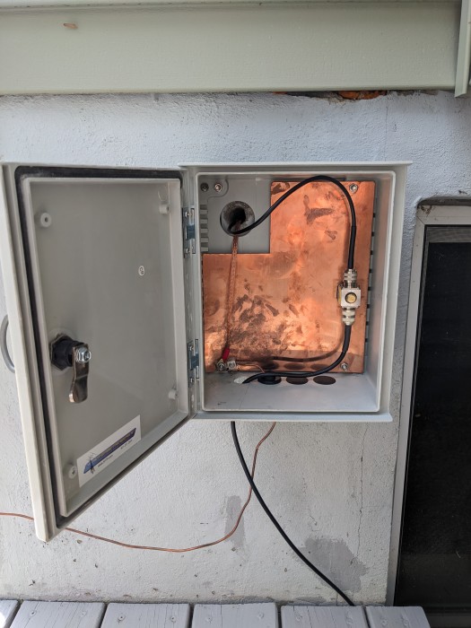
Here is a closeup of the grounding and lighting protection assembly.
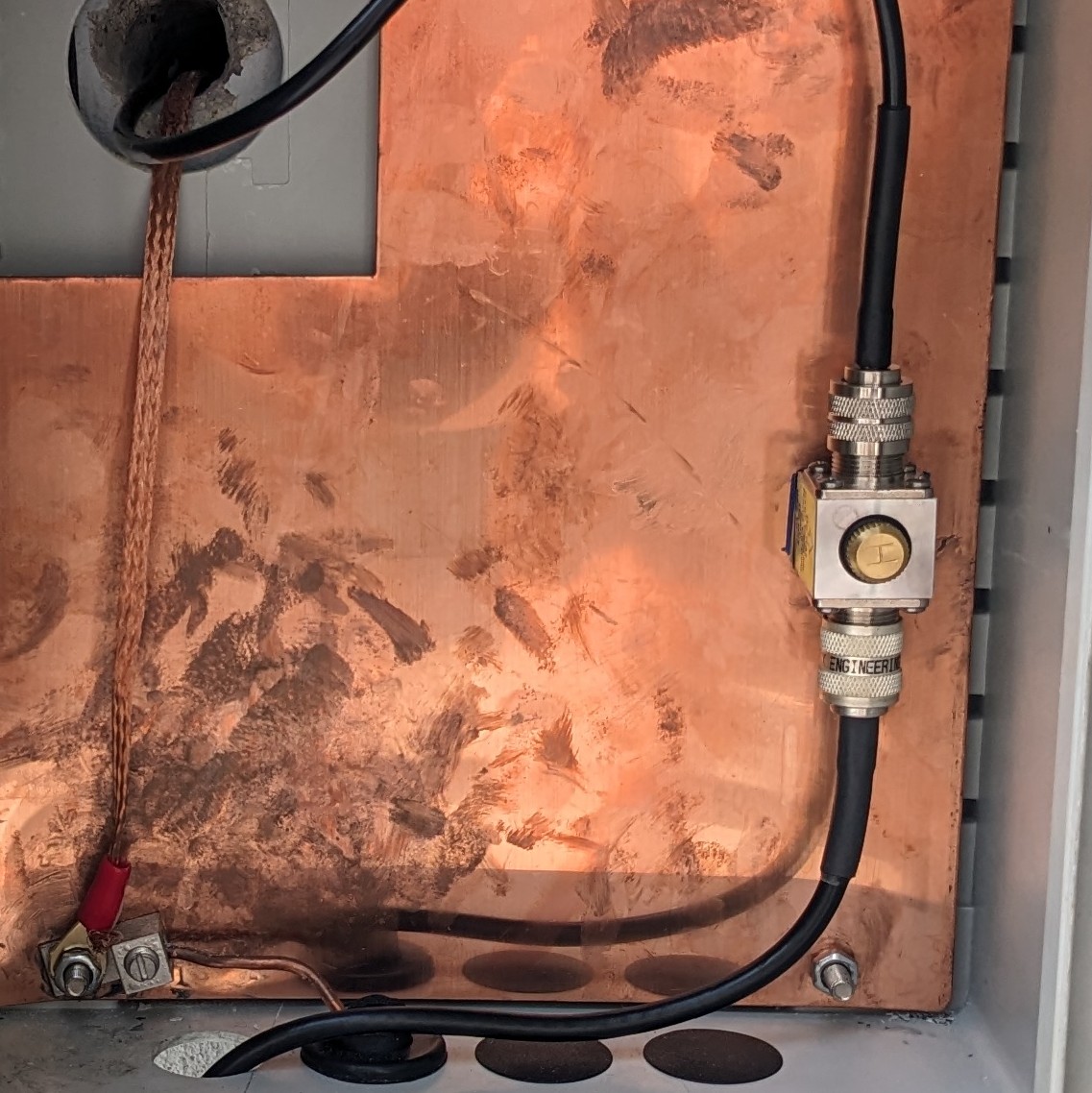
You can see:
- Large gauge bare, solid, copper wire coming in from the ground connection to the mechanical wire lug. The mechanical lug is connected directly to the copper sheet attachment screw.
- Braided copper wire going into the pass-through. The grounding wire is connected directly to the same copper sheet attachment screw.
- Mounted to the copper sheet is a lightning arrestor. I made sure to use Penetrox-A anti-oxidant connection grease between the aluminum arrestor and the copper sheet to prevent corrosion and improve connectivity.
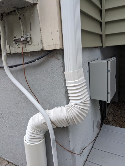
Here you can see the grounding wire’s short run to the bonding termination connection. The bonding termination cover is off to show the mechanical connector.
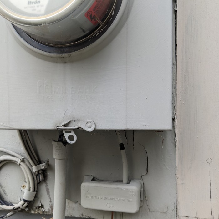
Here’s the bonding termination connection under my utility entrance panel. This all connects within the utility panel to my grounding rods. In this photo the bonding termination cover is back on.
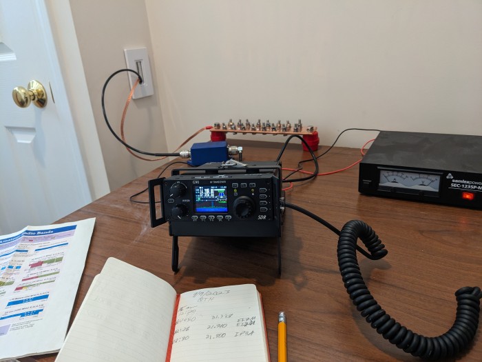
Inside the shack
Inside the shack you can see how the coax and copper ground run into my station.
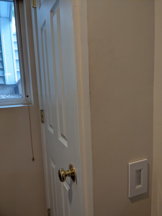
Here’s a photo that shows the window that, before this project, my end-fed antenna ran through. I didn’t want to crimp the antenna wire so it was always open a crack. This made for some drafty cold radio operations during the winter.
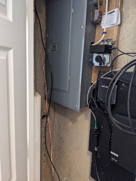
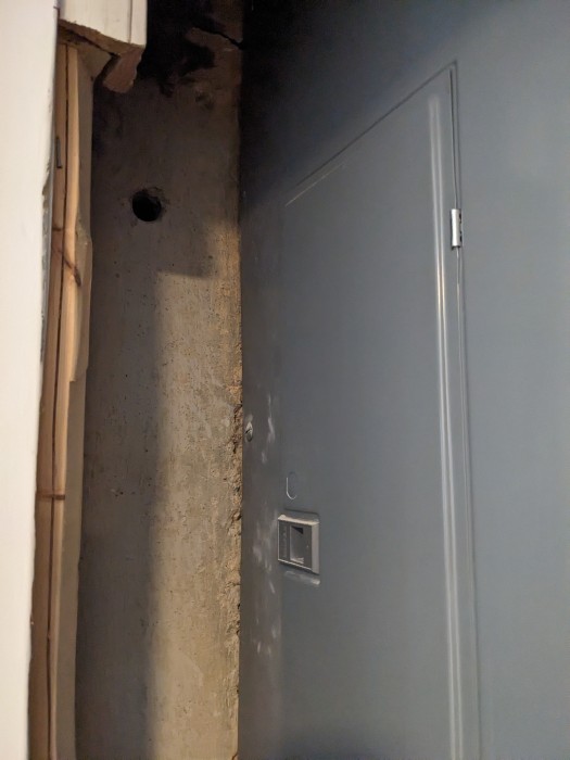
If you open the utility closet you can see that the coax feed-line and braided copper ground enter through the drilled hole. You can also see my internet and electrical junction boxes.
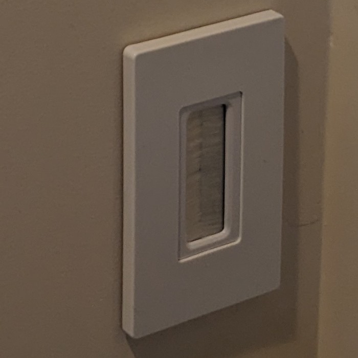
I installed a brush wall plate to make the entrance look tidy and prevent drafts.
It was very simple to connect it all to a copper grounding bus and my radio.
I’m very pleased with how this all turned out. In the end it was a simple project but what you see represents months of dreaming and thinking. I’m glad I took my time and did it correctly.
Supplies
The specialty box and grounding supplies were ordered from KF7P Metalwerks. He was incredibly helpful, answered my questions and designed the box according to my needs.
When I submitted my order, Chris (KF7P) quickly followed up with an email message to ask me a few questions so he could ensure I was getting exactly what I needed.
I sent him the following picture with a mocked-up box.
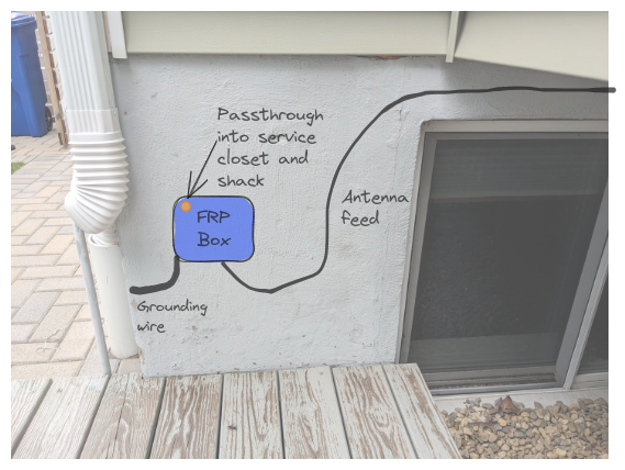
KF7P’s response - “Sure that will work… hole for cables going through the wall in the back upper left corner, and incoming grommets in the bottom.”
Resources
David Casler’s videos on grounding and HRCC’s videos were really helpful.
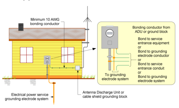
This grounding diagram, from “Antenna System Bonding and Grounding Requirements in the USA” by Whitham D. Reeve, is basically what I followed to design my own grounding and lightning protection system.
I went deep and read the Motorola Grounding Standard to be sure I understood concepts.